Appendix F
ASTP Launch Vehicles
As part of the joint agreement to use existing hardware, the Soviet and American launch vehicles employed in ASTP were standard boosters with proven records of performance. The Soviets utilized a modernized version of their Soyuz launch vehicle (Rakyeta nosityel soyuz), and the Americans used the Saturn IB. This appendix summarizes the information available concerning the performance characteristics of those boosters and the pre-flight preparations of the ASTP vehicles.
RAKYETA NOSITYEL SOYUZ-BACKGROUND
The Soyuz launch vehicle has a design lineage that can be traced to the boosters that placed the first Sputniks into orbit. In the early 1950s, the Soviets developed a kerosene and liquid-oxygen-fueled rocket motor for use in their first intercontinental ballistic missiles (ICBMs). When four of these motors were clustered together with two steerable vernier motors, the Soviets called the combination the RD 107 engine; when four motors were combined with four steerable motors the designation was RD 108. The initial ICBM, the SS-6 (Sapwood in NATO terminology), had four RD 107 units attached as strap-ons to a central core, which was powered by a RD 108. There was a total of twenty main rocket motors and twelve steering motors.
In Soviet practice, the four strap-on units (each 19 meters long and 3 meters in diameter at its base) constituted the first stage of the launch vehicle, while the central core (28 meters by 2.95 meters) was the second stage. Together these stages had been the workhorses of the Soviet space program since 1957. Starting with this basic combination, the Soviets had adapted their launch vehicle to different roles by varying the upper stages attached to it. Early satellites were launched using just the first two stages. Later Luna 1 through 3 and the manned Vostok series were launched using the Lunik third stage. Planetary probes and Voskhod were lifted into space by the SS-6 and the more powerful Venik third stage. Soyuz and Salyut were orbited by the SS-6 and third stages of respectively greater power. In the case of the joint project, the Soyuz 16 and 19 spacecraft were boosted by the latest version of the SS-6 and the Soyuz third stage. The aborted 5 April 1975 flight utilized an older version of the standard Soyuz launch vehicle.
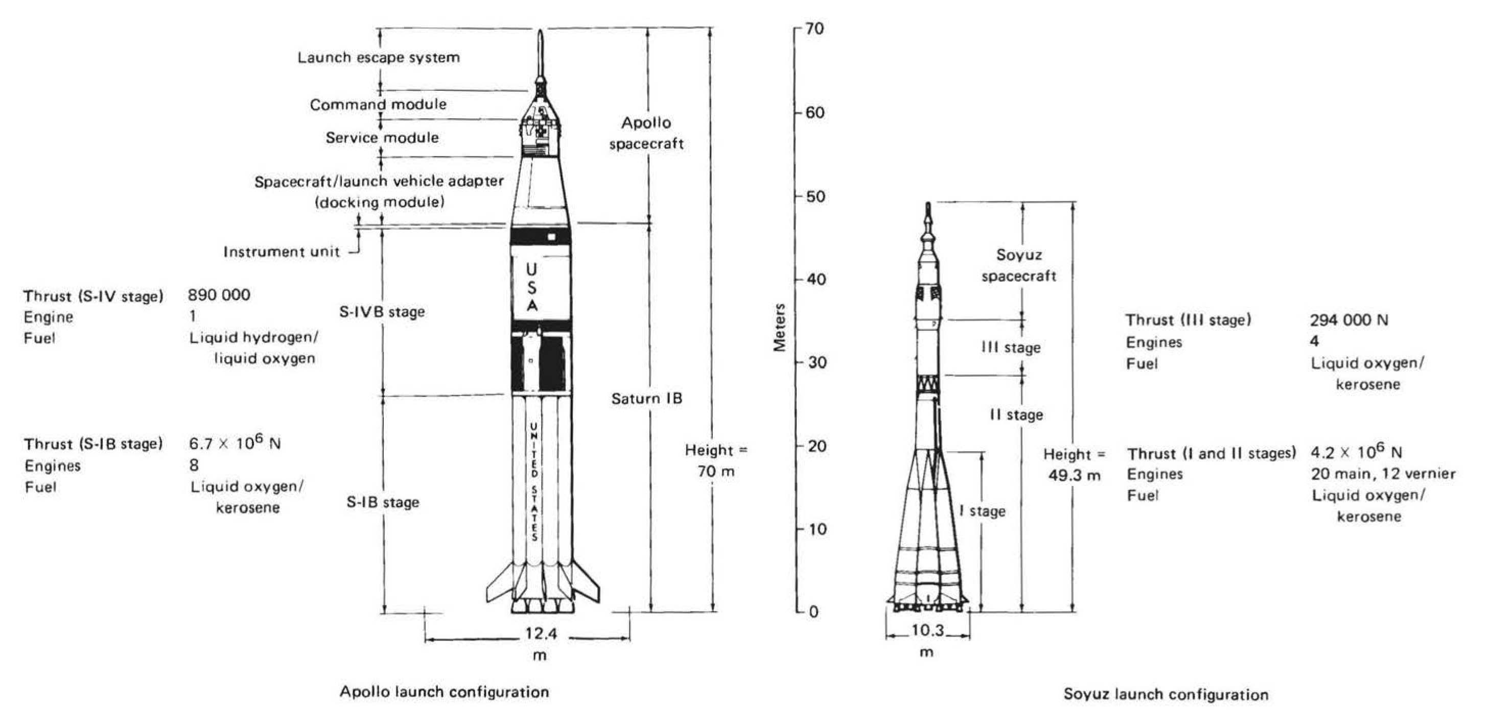
As employed in ASTP, the Soyuz launch vehicle had the following characteristics: each RD 107 produced approximately 845 000 newtons (190 000 pounds) of thrust, and the RD 108 produced about the same, for a total of 4.7 million newtons (950 000 pounds) at sea level; the Soyuz third stage (8 meters long and 2.6 meters in diameter) generated a vacuum thrust of approximately 294 000 newtons (66 000 pounds).*
At launch the engines of the first and second stages were ignited simultaneously. After 120 seconds of flight, the strap-on units were jettisoned. The central core continued to burn until 270 seconds after lift-off, thus accounting for the core being called a sustainer engine. At 270 seconds, the engines of the third stage were ignited, and the second stage was jettisoned. The spacecraft continued on its powered flight until 530 seconds when the third-stage engines were shut down and the spacecraft began its orbital flight around the earth.1
SATURN IB-BACKGROUND
A member of the Saturn launch vehicle family, the Saturn IB was conceived in 1962 as a more powerful (uprated) version of the Saturn I launch vehicle. The newer booster was capable of lifting larger payloads than its predecessor and was put to use during the Apollo earth orbital test missions and the command and service module (CSM) flights to Skylab and ASTP. All the lunar voyages of Apollo used the much more powerful Saturn V.* As employed in the ASTP mission, the Saturn IB’s first stage produced 6.7 million newtons (1.5 million pounds) of total thrust from its eight kerosene and liquid-oxygen-powered H-1 engines. Its second stage, the S-IVB, used a single J-2 engine fueled by liquid hydrogen and liquid oxygen to produce 890 000 newtons (200 000 pounds).
| Phase | S-IB | S-IVB | Instrument unit |
|---|---|---|---|
| Start of fabrication | 6 Sept. 1966 | 15 Feb. 1966 | Mar. 1967 |
| Completion of fabrication | 4 Jan. 1967 | 3 Jan. 1967 | Jun-68 |
| Completion of testing | 7 Mar. 1967 | 21 Mar. 1967 | June-Aug. 1968 |
| Static firing tests | 9-22 May 1967 | NA | NA |
| Start of plant storage | 30 Aug. 1967 | 23 Apr. 1967 | Jun-69 |
| Termination of plant storage | 30 Oct. 1972 | 12 Jan. 1971 | May-74 |
| Shipment to Kennedy Space Center (KSC) | 17 Apr. 1974 | 7 Nov. 1972 | May-74 |
| Start of KSC storage | 26 Apr. 1974 | 8 Nov. 1972 | May-74 |
| Termination of KSC storage | 4 Dec. 1974 | 8 Mar. 1974 | Dec. 1974 |
| Stacked on mobile launcher | 13 Jan. 1975 | 14 Jan. 1975 | Jan. 1975 |
| Phase | CSM 111 | DM 2 | DS 5 |
|---|---|---|---|
| Start of fabrication | Mar. 1967 | Apr. 1973 | Sept. 1973 |
| Completion of fabrication | Mar. 1970 | Jun-74 | Sept. 1974 |
| Plant storage completed | Jul-72 | NA | NA |
| Initiation of ASTP modifications | Aug. 1972 | NA | NA |
| Completion of ASTP modifications | Mar. 1973 | NA | NA |
| Completion of ASTP experiments/ATS 6 modifications | Aug. 1974 | NA | NA |
| Arrival at KSC | 7 Sept. 1974 | 29 Oct. 1974 | 3 Jan. 1974 |
The first Saturn IB launch (AS 201) took place in February 1966. Nine years later SA 210 lifted the ASTP CSM into orbit. Key dates in the life history of SA 210 are given in table F-1, and key dates in the life history of CSM 111, docking module (DM) 2, and descent stage (DS) 5 are given in table F-2. Once the launch vehicle and the spacecraft were received at KSC, the launch site team began to run a number of tests and began final flight preparations:
- S-IB and S-IVB stacked on mobile launcher
- 14 Jan.
- Manned altitude chamber tests with prime crew
- 14 Jan.
- Instrument unit and boilerplate CSM erection
- 16 Jan.
- Manned altitude chamber tests with backup crew
- 16 Jan.
- Mating of DM and CSM
- 27 Jan.
- Crew compartment fit and function test involving American and Soviet crews
- 10 Feb.
- Mating of DM to spacecraft lunar module adapter (SLA)
- 24 Feb.
- Mating of CSM to SLA
- 5 Mar.
- Replacement of cracked fins
- 11-19 Mar.
- Spacecraft delivery to Vehicle Assembly Building and erection on the stacked launch vehicle
- 17 Mar.
- Installation of launch escape system
- 22 Mar.
- Tests of lightning mast
- 23 Mar.
- Rollout to launch pad2
- 24 Mar.
SATURN IB STRESS CORROSION PROBLEM
According to a 1972 “Apollo Experience Report,” stress corrosion cracking had been the most common cause of structural-materials failures in the Apollo program. “The frequency of stress-corrosion cracking has been high and the magnitude of the problem, in terms of hardware lost and time and money expended, has been significant.”*3 Since some of the alloys used in the construction of the Saturn IB launch vehicle were known to be susceptible to stress corrosion, routine inspections had long been a standard procedure. After the discovery in late 1973 of cracks in eight stabilizing fins of the S-IB stage used to launch Skylab 4, the SA 210 fins were given special attention. A crack was first noted on a test fin undergoing a stress corrosion check at the Michoud Assembly Facility, New Orleans. A subsequent, more detailed investigation of all eight fins of SA 210 at KSC on 19 February 1975 discovered cracks in the hold-down fittings in two of the fins.* In a telex to Professor Bushuyev, Glynn Lunney explained that “this fitting serves no purpose in flight, but supports the launch vehicle on the hold-down arms of the mobile launcher. The critical load on this fitting would occur during ‘rebound’ if the launch were to be aborted after engines were started and before hold-down arms are released. Fins without cracks have been modified to reduce the stress in the area where cracks initiated. Portions of the fittings were also treated to provide compressive stresses in the surface which also prevents cracking. A fin with these fixes was tested to 142 percent of the design rebound load. Modified fins are now being installed and there is no delay in launch schedule.” After the replacement of all eight fins, which solved the stress corrosion problem, this issue was certified to have been corrected during the Headquarters Flight Readiness Review, 12 June 1975.6
LAUNCH OPERATIONS
Table F-3 lists the schedule of events prior to the launch of both Soyuz. and Apollo.
| Time1 | Time to launch | Procedure |
|---|---|---|
| 13-Jul | ||
| 10:30 a.m. | Apollo: T - 42 hr, 30 min | Start Apollo countdown. |
| 11:00 a.m. | Soyuz: T - 34 hr, 30 min | First Soyuz launch vehicle readied for propellant loading; second Soyuz also on its launch pad. |
| 5:00 p.m. | Apollo: T - 35 hr, 30 min | Cryogenic loading of Apollo fuel cells begun; completed at 11:00 p.m. |
| 15-Jul | ||
| 2:20 a.m. | Soyuz: T - 6 hr | Soyuz launch vehicle batteries installed. |
| 4:20 a.m. | Soyuz: T - 4 hr S | First Soyuz launch vehicle propellant loaded. |
| 6:20 a.m. | oyuz: T - 2 hr | U.S.S.R. Soyuz crew enters first Soyuz spacecraft and U.S. mobile service structure is moved from the U.S. Apollo launch pad. |
| 6:50 a.m. | Apollo: 7- 9 hr | Begin clearing blast danger area for launch vehicle propellant loading. |
| 7:35 a.m. | Soyuz: T - 45 min | The U.S. reports the last Apollo status “Go for Soyuz launch.” |
| 7:42 a.m. | Apollo: T - 8 hr, 8 min | Initial target update to the launch vehicle digital computer for rendezvous with Soyuz. |
| 8:19:40 a.m. | Soyuz: T - 20 s | The U.S.S.R. Soyuz is launched and confirmation by voice follows immediately from the U.S.S.R. control center. |
| 8:30 a.m. | Soyuz: T + 10 min | The U.S. starts the Apolio launch vehicle propellant loading: liquid oxygen in first stage and liquid oxygen and liquid hydrogen in second stage; continues for 4 hr and 22 min. |
| 10:35 a.m. | Apollo: T - 5 hr, 15 min | Flight crew alerted. |
| 10:50 a.m. | Apollo: T - 5 hr | Crew medical examination. |
| 11:20 a.m. | Apollo: T - 4 hr, 30 min | Brunch for crew. |
| 12:20 p.m. | Apollo: T - 3 hr, 30 min | 30-min built-in hold. |
| 12:44 p.m. | Apollo: T - 3 hr, 6 min | Crew leaves manned spacecraft operations building for LC-39 via transfer van. |
| 1:02 p.m. | Apollo: T - 2 hr, 48 min | Crew arrives at Pad B. |
| 1:10 p.m. | Apollo: T - 40 min | Start flight crew ingress. |
| 1:59 p.m. | Apollo: T - 1 hr, 51 min | Start space vehicle emergency detection system test. |
| 2:29 p.m. | Apollo: T - 1 hr, 21 min | Target update to the launch vehicle digital computer for rendezvous with Soyuz. |
| 2:52 p.m. | Apollo: T - 58 min | Launch vehicle power transfer test. |
| 3:05 p.m. | Apollo: T - 45 min | Retract Apollo access arm to standby position (12°). |
| 3:08 p.m. | Apollo: T - 42 min | Final launch vehicle range safety check (to 35 min). |
| 3:15 p.m. | Apollo: T - 35 min | Final target update to launch vehicle digital computer for rendezvous with Soyuz. |
| 3:20 p.m. | Apollo: T - 30 min | The U.S.S.R. provides a nominal Soyuz status “Go for Apollo launch.” |
| 3:35 p.m. | Apollo: T - 15 min | Maximum 2-min hold for adjusting lift-off time; spacecraft to full internal power. |
| 3:42 p.m. | Apollo: T - 8 min | The U.S.S.R. reports the last Soyuz status “Go for Apollo launch.” |
| 3:44 p.m. | Apollo: T - 6 min | Space vehicle final status check. |
| 3:45 p.m. | Apollo: T - 5 min | Apollo access arm fully rejected. |
| 3:47 p.m. | Apollo: T - 3 min, 7 s | Firing command (automatic sequence). |
| 3:49 p.m. | Apollo: T - 50 s | Launch vehicle transfer to internal power. |
| Apollo: T - 3 s | Ignition sequence start. | |
| Apollo: T - 1 s | All engines running. | |
| 3:50 p.m. | Apollo: T - 0 s | Lift-off. |
1 EDT.
NOTES
- Reliable data on Soviet launch vehicles are hard to find. This summary is based on the following sources: [Soviet Academy of Sciences], “Apollo-Soyuz Test Project; Information for Press,” 1975, pp. 76-78; Charles S. Sheldon II, “The Soviet Space Program Revisited,” TRW Space Log (1974), pp. 2-19; Peter L. Smolders, Soviets in Space (Guildford and London, 1973), pp. 62-68; U.S. Congress, Senate, Committee on Aeronautical and Space Sciences, Soviet Space Programs, 1966-70; Staff Report, 92d Cong., 1st sess. (9 Dec. 1971), pp. 130-132 and 559-563; and ASTP mission commentary transcript, MC 9/1, 15 July 1975.
- NASA, MSFC, KSC, et al., “Saturn IB News Reference,” Dec. 1965 (changed Sept. 1968); and Ellery B. May to Edward C. Ezell, 24 Feb. 1976, with enclosed data on SA 210.
- NASA, JSC, Robert E. Johnson, “Apollo Experience Report, the Problem of Stress-Corrosion Cracking,” TN S-344 (MSC-07201), review copy, July 1972, p. 1.
- NASA, MSFC, “Design Guidelines for Controlling Stress Corrosion Cracking,” 15 June 1970; [Chrysler Corp.], C. C. Davis to R. J. Nuber, memo, “Submittal of CCSSD ECP’s EP 12112 and EP 12112T-Additional Structural Components Requiring Stress Corrosion Inspection and Supplemental Test ECP,” 10 Jan. 1974; NASA, MSFC, “ASTP Launch Vehicle Stress Corrosion Review,” 11 Nov. 1974; R. J. Schwing-hammer to Ellery B. May, memo, “Stress Corrosion Assessment of AS-210,” 14 Nov. 1974; NASA, MSFC, “ASTP SA-210 Launch Vehicle Design Certification Review,” 15 Nov. 1974; and NASA News Release, KSC-27-75, “Two ASTP Saturn IB Fins to Be Replaced,” 25 Feb. 1975.
- TWX, Glynn S. Lunney to Konstantin Davydovich Bushuyev, 17 Mar. 1975.
- NASA News Release, MSFC, 75-43, “All Eight Saturn I-B Fins to Be Replaced,” 28 Feb. 1975; and NASA, HQ, “Saturn IB Stress Corrosion,” General Management Review Report, 17 Mar. 1975.
*These thrust figures are calculated from data made available by the Soviets.
*Both the Saturn IB and its predecessor helped to lay the foundation for the Saturn V program. The Saturn V had three stages-the S-IC, the S-II, and the S-IVB. The Saturn IC had five kerosene and liquid oxygen F-1 engines producing 33.4 million newtons (7.5 million pounds), while the Saturn II stage produced 4.5 million newtons (1 million pounds) with five J-2 engines. The Saturn IVB was the same stage as used on the S-IB launch vehicle.
*When certain metal alloys are exposed to a corrosive environment while at the same time they are subjected to an appreciable, continuously maintained, tensile stress, rapid structural failure can occur as a result of stress corrosion. This is known as stress corrosion cracking and is characterized by a brittle-type failure in a material that is otherwise ductile.